Using Micro-ducts in FTTX Networks
Author: admin | Date: April 26, 2017 | Please Comment!Key in the deployment of any fiber-to-the-X (FTTx) passive optical network (PON) infrastructure is to maximize the number of units attached to a single optical distribution network (ODN). A greater number of units attached to the ODN reduces the overall cost per unit. But also, key is to create a passive network that is flexible to adjust to the growth and bandwidth demands of the subscriber base. The use of micro-duct introduces flexibility that is not easily achieved with traditional build techniques. These are inclusive of:
- Passive System Attenuation (PSA) losses
- Optical-Signal-to-Noise Ratio (OSNR)
- Financial cost for and types & quantities of materials
- Maintenance costs (Operational Expenditures)
- Defer fiber optic cable costs till ‘take-rate’ requires
- Allowing for creation of redundancy
- Allowing for use of fiber optic cable only upon subscription
- Reduces and or eliminates field splices by allowing ‘home runs’ from the fiber distribution hub (FDH)/fiber access terminals (FAT) to the subscriber optical network terminal (ONT)
Of course, there are drawbacks with the use of micro-duct, some of which are:
- Lack of wide experience for the installation and maintenance
- Specialty equipment and tools needed for installation and maintenance
- Different types of fiber optic cabling requiring retraining of technicians on how to work with
It should also be understood that the use of micro-duct is not limited to underground applications. It can also be used in aerial applications. Albeit a bit more difficult with transitions and dips due to bend ratio it is still very much viable. This paper is focused in on underground applications, however the same philosophy can be applied to aerial applications. The only thing that truly changes is the device placement and, of course, the construction technique. However, the savings reflected are applicable to either underground or aerial use of micro-ducts.
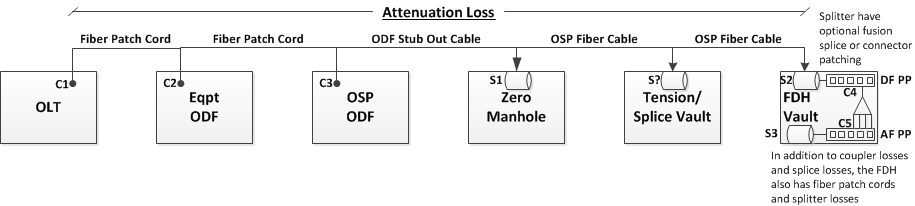
Figure 1: Typical OLT to FDH Route
A typical FTTx route will:
- Start at the optical line terminal[i] (OLT) (C1) – feed to the equipment optical distribution frame (ODF) (C2) normally via fiber optic patch cords.[ii]
- Should be noted that the connection at the equipment is also a point of high optical signal-to-noise (OSNR) ratio due to back scattering and reflectance.
- When calculating the overall cable length, the length of this cable (or patch cord) must also be taken into consideration.
- From the equipment ODF, a fiber optic patch cord is then ‘jumped’ over to the outside plant ODF (C3).[iii] The outside plant (OSP) ODF normally will have a cable stub out, thus the connectors are factory terminated at the ODF.
- The OSP ODF cable stub out will be routed to the zero manhole[iv] where it is fusion spliced (S1) to the outside plant fiber optic cable (OSP-FOC) which is routed to the respective fiber distribution hubs (FDH).
- Depending upon length of the route and the fiber optic cable reel length, an intermediate splice (S?) might be required. The overall outside diameter of the cable will determine the total maximum length that cable reel[v] can hold. When ordering cable or pulling cable reels from the warehouse, care should be exercised to attempt to get proper lengths to minimize fiber splicing requirements.
- The final point is the fiber distribution hub (FDH).[vi] There are many configurations of the FDH. Some that are in splice enclosure structures that can be placed below-grade or aerially, some in cabinets, and some in pedestals. It does not matter what the outer structure looks like, they all perform the same function:
- Termination of the Distribution Feeder (DF) into a DF patch panel (normally a stub out is provided so to splice (S2) the DF to the OSP FOC).
- The DF patch panel is then ‘jumped’ to the splitter (1:2, 1:4, 1:8, etc.) (C4).
- The splitter then splits the signal and is connected via factory terminated connectors to a coupler on the access fiber patch panel.
- The AF patch panel is then ‘jumped’ from the split ratio ports to the access fiber (AF) optic cable (C5), which is normally a cable stub from the access network patch panel which is then spliced to the access network OSP cable (S3).
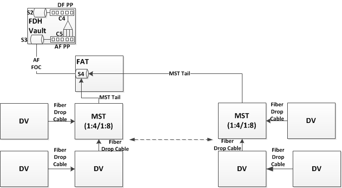
Figure 2: Typical example of Access Fiber Routes using MSTs
The typical access fiber network consists of:
- Starting at the FDH, the access fiber cable is spliced (S3) to the FDH access fiber patch panel stub out and is run to the fiber access terminal (FAT).
- The total number of FATs is determined by the number of strands within the access fiber optic cable and the targeted number of units to be served by that access fiber cable.
- At the FAT, a splice enclosure is placed and the multi-service terminal (MST) fiber optic tail is spliced to the access fiber cable strand.
- Based on the MST split ratio will determine the number of units served by that access fiber strand, which is connected back at the FDH split ratio.
- The MST is the final split ratio of the optical distribution network (ODN) and is connected to the served units via drop cables (i.e. DLX).
- To ease the distribution of the DLX cables, drop vaults are often placed too allow servicing the respective units, thus decreasing the complexity when connecting subscribers after the build project is completed.
The above reflects the most common typical configuration for FTTX network using traditional HDPE conduit and a high-density multi-strand fiber optic cable, with FDH and MST connecting the subscribers back to the OLT, thus creating the ODN. The use of multi-duct can provide alternatives for each or both configurations, which shall be addressed below.
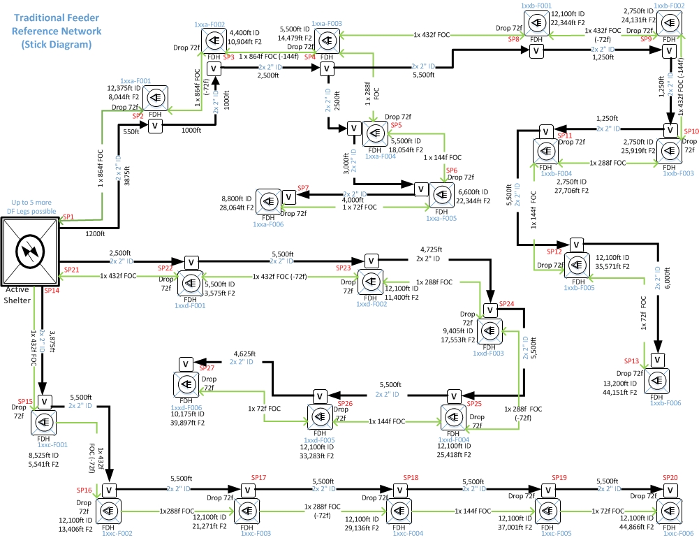
Figure 3: Typical Distribution Feeder Network to FDHs
Figure 3 (above) shows a typical distribution feeder network that uses a tapering process for the fiber optic cable and SDR11 HDPE inner-duct for placement.[vii] As shown, without considering any reel-end splice requirements, this requires twenty-seven (27) splice points which results in losses and mid-span cable sheath breaks. Taking into consideration the exact same configuration but replacing the tapering fiber optic cable and SDR11 HDPE inner-duct with a 7-way 14/10mm micro-duct would allow for elimination of some fiber cable splices. As reflected in Figure 3, a target of 72-fiber strands to be delivered to each FDH with the fiber optic cable being placed in 2-inch SDR11 HDPE inner-ducts.[viii] Fiber optic micro-cables, with up to 192-fiber strands, are available that can be placed into the 10/14mm micro-duct. This allows for a ‘home-run’ of the fiber optic cable directly from the Active Shelter to the FDH. As shown in the below diagram, this would eliminate most of the cable-end splices and all the cable sheath breaks and fiber strand extractions, effectively making only 4 cable-end splices required. When considering cable preparation time and splicing this is a potentially significant cost savings, as well as time savings. Take this aspect and the materials (splice enclosures, trays, etc.) and the passive system attenuation losses of splices and this reflects a potential technical and commercial savings.
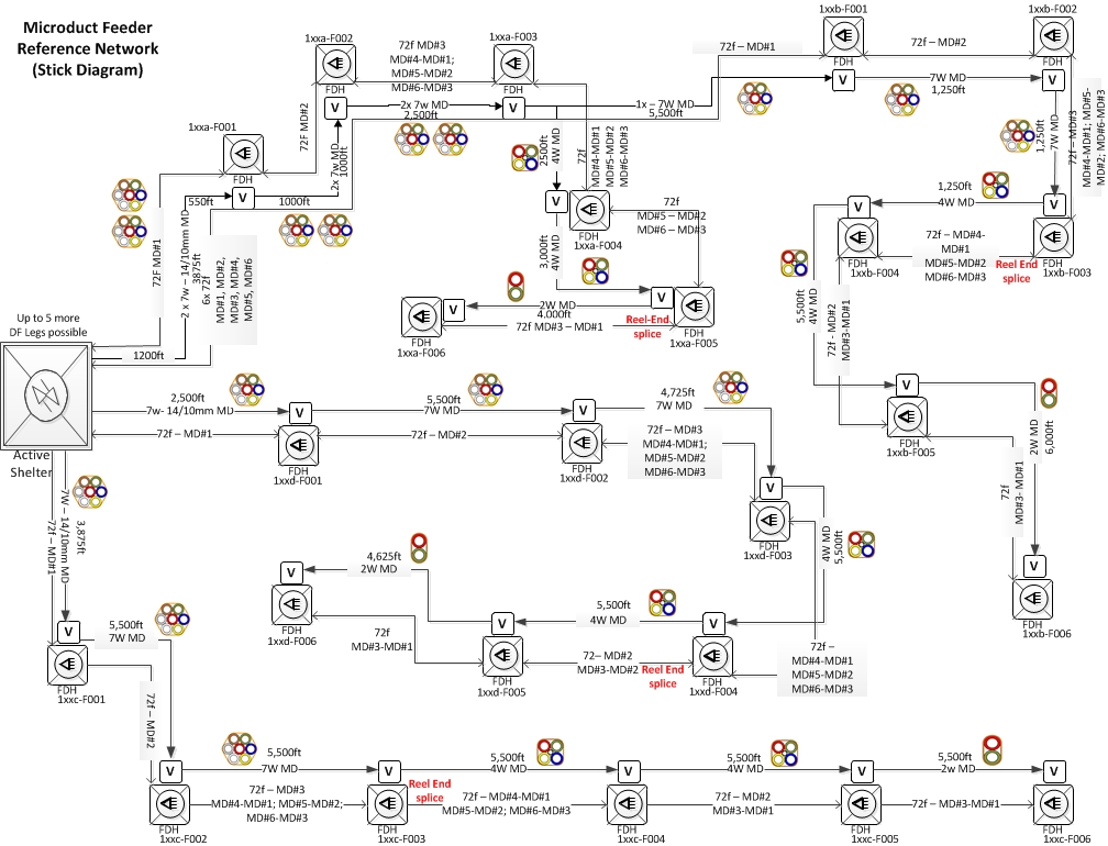
Figure 4: Micro-duct Distribution Feeder Network to FDHs
Figure 4 (above) reflects the following type of micro-duct and fiber architecture:
- From the Active Shelter, placement of a 7-way 14/10mm micro-duct bundle and extracting one (1) micro-duct tube at each FDH. With this architecture, there are six (6) FDHs along the route, thus there would be one spare micro-duct for future use or specialties along the route.
- With the use of the 14/10mm micro-ducts, fiber optic micro-cables can be used. Micro-cables come with up to 192-fiber strands, as such even should additional fibers be needed at the FDH for specialties, it does not present a limitation on a normal basis.
- One 14/10mm micro-duct tube is allocated to one of the FDHs. If additional capacity is known at the time of design, different sizing of fiber optic cable can be specified thus not even mandating use of the spare micro-duct tube.
- Placement within the 14/10mm micro-duct tube of a home-run fiber optic cable allows for reduction of cable sheath breaks, which weakens the integrity of the cable, as well as either eliminating the need to ‘taper’ the cable along the pathway (Figure 3) or non-tapered resulting in excessive ‘abandoned’ fiber strands along the route.
- Of course, this does result in a larger amount of fiber cable due to the home run nature from each FDH back to the Active Shelter, as such this could result in a bit higher cost, but this cost must be compared to the commercial savings in labor (splicing) and materials (splice enclosures, trays, etc.).
i. An alternative is to use a higher fiber strand rate in the micro-ducts and to taper the cable as required thus reducing some of the footage and even potentially the number of micro-ducts required to serve. There are many options. You just must think through the objectives and impacts.
- With the air-blown solutions, the use of micro-duct and micro-cable, cables can be placed with considerably longer distances without tension relief, thus reducing the number of tension relief vaults required. Additionally, the duct branch closures can be direct buried, as a properly installed micro-duct joint, should not require any future maintenance or reopening. This improves the public acceptance of the infrastructure as it does not create consistent aesthetically displeasing vaults.
- As this is for FTTx applications, many times the distribution feeder routes shall be run adjacent to the access fiber routes. As such, due to the nature of normal DF fiber, slack loops are placed in various vaults that it runs through but this requires larger vaults to be put into place, even though the access network does not require it. The use of micro-duct, even with a duct closure mandate, the typically smaller access vaults are satisfactory, thus not requiring larger aesthetically displeasing vaults to be dominantly placed.
- The placement of a ‘spare’ micro-duct tube, along the whole distance, allows for growth should the number of fiber strands originally allocated prove inadequate. Using the spare tube and blowing in larger fiber cable to the targeted FDH, allows for placement to occur without new civils work, without the potential of damaging the existing cable, reduction of fiber splices, etc. Then, once the new cable is active and cut-over, the old micro-duct tube can have the fiber cable removed and become the spare micro-duct tube for all the FDHs. And of course, if all the FDHs need upgrading, this process can be repeated for each FDH.
Figure 4 (above) reflects purely replacing the distribution feeder infrastructure but keeping the core FDH architecture in place. While this does allow for improved performance, it does still introduce the losses at the FDH. While this is a significant improvement, it is not the final or ultimate solution.[ix] One challenge can be that companies have already made an investment in the distribution feeder environment and placed the traditional distribution feeder architecture (Figure 3) already. As a result, the above micro-duct solution may not be a potential to be used, thus the only place that might justify visiting a micro-duct solution is in the access network infrastructure. This is understandable and will be explored below. Figure 5 (below) shows the continuation of the concept of using a high-density FDH terminating the distribution feeder and creating the access network. In a future article we will explore the concept of elimination of the high-density FDH to an alternative that the use of micro-ducts allows. This would reduce costs associated with these high density FDHs as well as other materials and labor costs. One of the key factors that these alternatives provide is addressing the aesthetics within the neighborhood after the build project is completed. In consideration of Figure 3, the target is for each FDH to serve approximately 768 units, with a target of the ODN split ratio to serve at least thirty-two (32) units. To achieve this, and in consideration of the normal topography of the access network, the following is one of the ways to address a micro-duct solution feeding from a high-density FDH configuration as shown in Figures 3 & 4 above.
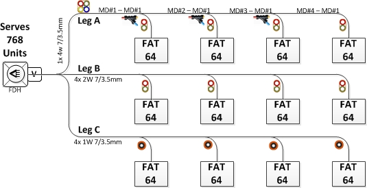
Figure 5: Access Network Solutions using Micro-duct
Figure 5 shows three different solutions for serving the respective serving area via micro-ducts.
- Leg A utilizes a 4-way micro-duct bundle. This is a good application when the allowed running line allows for placement of the fiber access terminals (FAT) vaults so that the micro-duct route goes directly through the vaults.
- Albeit this does mean a bit more work to perform mid-span breaks in the conduit bundle and using enclosures that increases the cost of the service.
- Another reason to use this method is when figuring cost for placement, on a normal basis the charge is for opening the trench/bore + one conduit, any additional conduit there is an ‘Adder’ fee, thus this would prevent the adder fee potential.
- Leg B utilizes a 2-way micro-duct bundle, thus providing 100% redundancy to each FAT.
- This is a good application for when the FAT vault is not in alignment with the approved running line as this will eliminate any splicing of the conduit that would be required as in Leg A.
- This method also provides the greatest ease to add ‘new’ fiber to the FAT should the need arise in the future.
- This could increase the cost for placement as unless it is negotiated to have multiple micro-duct bundles placed at the same time with staged interruptions, then ‘Adders’ could apply to this configuration.
- Leg C utilizes a 1-way micro-duct bundle to each FAT. Unlike Leg B, this configuration provides no redundancy or non-disruptive growth potential.
- This is a good application for when the FAT vault is not in alignment with the approved running line as this will eliminate any splicing of the conduit that would be required as in Leg A.
- This could increase the cost for placement as unless it is negotiated to have multiple micro-duct bundles placed at the same time with staged interruptions, then ‘Adders’ could apply to this configuration.
- These solutions use a 7/3.5mm micro-duct. This will allow a Nano-cable of up to 12-fibers to be placed from the FDH to the FAT.
- Within the FAT a small fiber access terminal can be placed that could be the first split ratio, a spliced fiber from the FDH to the MST, or last split ratio with home run drop cables.
Of course, this does not get the fiber optic cable to the subscriber unit. So, let’s explore the final leg of taking the fiber from the FAT to the subscriber units, following the premise of Figure 3, a centralized high-density FDH.
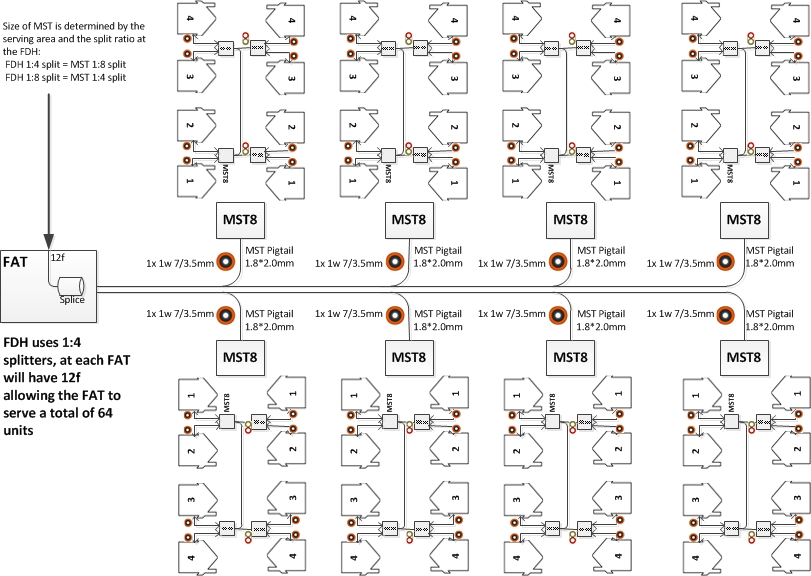
Figure 6: Access Network using Micro-duct: FAT to MST to ONT
Figure 6 reflects from a single FAT that a total of sixty-four (64) units can be served using the Figure3 centralized FDH to serve 768 units. Additionally, it continues the trend of using the hardened MST as the last splitter point.
- With the FDH using a 1:4 split ratio and having 12f delivered to the FAT, a total of three (3) 1:4 split ratio can be served from the FAT. However, as a normal rule of thumb, the desire is to always provide spares, so instead of utilizing 100% of the fiber split, 8-fibers will be allocated with the remaining 4-fibers designated as spare or special usage fibers at the FAT.
- From the FAT, a 1-way 7/3.5mm micro-duct shall be placed to the MST vaults. The MST pigtails shall be routed through these micro-ducts to the FAT where they will be spliced to one of the allocated fiber strands.
- From the MST vault:
- Two (2) 1-way 7/3.5mm micro-duct shall be installed to the nearest units to the MST vault.
- One (1) 2-way 7/3.5mm micro-duct shall be installed ‘across the street’ to a drop vault (DV). (Refer to Figure 6)
- From the Drop Vault, two (2) 1-way 7/3.5mm micro-duct shall be installed to the nearest units to the MST vault.
- From the MST designated port, each served unit (total of 8) a drop cable shall be installed that on the MST side has a hardened connector and on the units’ optical network terminal (ONT) a terminated ferrule.[x]
- The terminated ferrule end shall then have the jacket and boot placed by the installing technician.
As has been reflected above, there are various means to use micro-ducts within the FTTx architecture that if properly planned and installed can result in cost savings and technical improvement. Future articles shall explore more detailed end-to-end solutions and costing models. However, it is hoped that this article gave the readers ‘food-for-thought’ on methods that could be used to improve their FTTX architecture.