Author: admin | Date: May 14, 2017 | No Comments »

Duration:     5 days

Training Format:   50% Instructor-Led – 50% Hands On Exercise

Daily Class Schedule: Session 1:  8:00AM – 11:30AM CDT

Lunch Break: 11:30AM – 1:00PM CDT

Session 2: 1:00PM – 4:30PM CDT

Course Overview:

This course shall provide the Attendees with a focus on the optimal manner in which to design outside plant (OSP) networks to provide service to the Subscribers.  It assumes the Attendees has a core knowledge of fiber optics, outside plant, and FTTX architecture, however shall conduct a baseline refresher on the topics.  Course will discuss in detail the manner in which optimal fiber-to-the-X (FTTX) networks are designed, based on a flexible growth pattern (take-rate), thus allowing for maximum optimization of optical distribution network (ODN) ports on the optical line terminal (OLT).  Course shall address different construction techniques and materials that are currently being use, as well as those technologies that are on the rise that could represent cost savings.

Who would benefit from this course:

  • FTTX Outside Plant Designers/Engineers
  • Municipalities considering FTTX within their community
  • FTTX Construction Inspectors
  • FTTX Construction Managers
  • FTTX Construction Contractors

Course Modules:

Module 1: Baseline Refresher

Module 2: ODN Elements

Module 3:  OSP Construction Techniques Overview

Module 4: OSP Materials

Module 5: Fiber Materials

Module 6: Design: OSP Pathways & Spaces

Module 7: Design: OSP Underground Pathways
Module 8: Design: OSP Direct Buried Pathways

Module 9: Design: Micro-Trenching

Module 10: Design: OSP Aerial Pathways

Module 11: Design: OSP Aerial Construction Practices

Module 12: Design: OSP Spaces

Module 13: Design: OSP Splicing

Module 14: Design: OSP RoW


 For additional information please contact David Rottmayer at drottmayer@unicorncom.net.


On-site training course is possible.

Author: admin | Date: May 12, 2017 | No Comments »


Introduction

In today’s outside plant (“OSP”) environment, the tendency to ‘underground’ the infrastructure has been growing, especially within metropolitan areas but also in areas with severe weather conditions.  This trend has created an environment where both safety and aesthetic is addressed but has created a series of new challenges.

Previously, public utilities, such as natural gas – water – storm drain – sewage infrastructure was placed underground, while electric and telecommunications infrastructure was placed aerially.  However, this creates a less than aesthetically pleasing environment as well, in severe weather conditions, increases the probability of disruption and/or extended outages.  With these aspects in consideration, placement of the electric and telecommunications infrastructure has been trending toward being ‘undergrounded’.

This migration to underground all utilities has created a situation where the underground pathways have become highly congested which creates a serious problem for the placement of the newer OSP infrastructure, whether that is public utilities or telecommunications infrastructure.

Another aspect, that creates a major challenge to the ability to place new OSP infrastructure underground, is that, in many circumstances, the previous underground infrastructure was poorly – if at all – documented, thus making placement of new subsurface infrastructure extremely challenging as well as dangerous.  This is a common problem whether working in ‘developed’ or ‘developing’ countries.

Effectively, without knowing what is below the surface at time of engineering, this leaves the as-built to be the definitive document of what is below ground.  However, frequently, underground utility lines are put in the ground not according to design but wherever it is easiest and cheapest to build them.  As-builts of underground infrastructure are often ‘as-designed’ not ‘as-constructed’ thus are unreliable from the very beginning.   And if the ‘as-builts’ are provided, very few are geolocated to a mapping grade level and almost never reflect depth or crossings of other utilities.  Why is this an issue? In the US alone:

  1. Underground utility line hit every 60 seconds
  2. Annual cost due to utility damage ranges in the Billions of US dollar
  3. Inaccurate records and locating
  4. Utilities not marked
  5. Crowding within the rights-of-way

Additionally, with the current political environment, globally, even should the underground infrastructure be properly documented, many companies are unlikely to share as-built documentation with third parties.  In many cases, it is illegal to share underground infrastructure maps due to the threat of terrorist attacks against the infrastructure.

Example: Within the US, the Department of Homeland Security (“DHS”) restricts access and distribution of any natural gas infrastructure.  As such, while they maybe well documented, no third party outside of the operating gas company may have access to these files, unless obtaining written approval from DHS.

In many countries, the need to ‘locate’ the subsurface utility infrastructure is mandated by law, whereas, in other countries this is not mandated.  Regardless of the law mandates, the need to identify the subsurface infrastructure is critical, especially when using construction techniques such as horizontal directional drilling (‘HDD”).  However, even if open trench and or micro-trenching is to be used as the construction technique, prior knowledge of where the existing subsurface infrastructure is critical.

Even with ‘locates’, with the use of direct-buried fiber optic cables, HDPE conduits, and clay tiles, these are non-conductive, as such if the ‘tracer wire’ is improperly, if at all, installed, then these utilities become ‘unlocatable’ as such significantly increases the cost to build and restore, let alone the increased risk factor.

Subsurface Utility Engineering

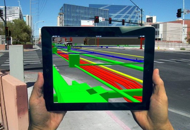
Subsurface utility engineering (“SUE”) is a highly efficient, nondestructive engineering practice that combines geophysics, surveying, civil engineering, and asset management technologies.  Used appropriately and performed correctly, SUE identifies existing subsurface utility data, maps the locations of underground utilities, and classifies the accuracy of the data based on standardized quality levels.  The data allows for developing strategies and making informed design decisions to manage risks and avoid utility conflicts and delays.  If a utility conflict arises, viable alternatives can be found to resolve the issue before any damage is done and usually at a lower cost.

In 2003, the American Society of Civil Engineers (“ASCE”) published the ‘Standard Guideline for the Collection and Depiction of Existing Subsurface Utility Data.”  This standard formally defines SUE and sets standard guidance for collecting and depicting underground utility information.

According to the American Society of Civil Engineers (ASCE), the definition of subsurface utility engineering is:

“A branch of engineering practice that manages certain risks associated with subsurface utilities via: utility mapping at appropriate quality levels, utility coordination, utility relocation design and coordination, utility assessment, communication of utility data to concerned parties, utility relocation cost estimates, implementation of utility accommodation policies and utility design.”

Economics of SUE

According to a US Department of Transportation (USDOT) sponsored survey conducted by Purdue University in 1999[1], two broad categories of savings emerged from using SUE – quantifiable and qualitative savings.  The Purdue study quantified a total of USD4.62 in avoided costs for every USD1.00 spent on SUE.  Although qualitative savings were not directly measurable, the researchers believed those savings were significant, and arguably many times more valuable than the quantifiable savings.

According to a 2004 study, commissioned by Ontario Sewer and Watermain Contractors Association and conducted by the University of Toronto to study the impact of SUE on large infrastructure projects in Ontario, determined that USD3.41 can be avoided for every USD1.00 spent on SUE.

In 2007, the Pennsylvania Department of Transportation (PennDOT) commissioned Pennsylvania State University (Penn State) to study savings on Pennsylvania highway projects that used SUE in accordance with the mapping provisions of the American standards.  In their unpublished report, Subsurface Engineering Manual, Penn State found a return on investment of USD21.00 saved for every USD1.00 spent on SUE.[2]

In 2010, the University of Toronto accomplished an Australian study, over a period of 12-months and took an in-depth look at 9 large municipal and highway reconstruction projects that developed an enhanced depiction of buried utilities.  Based on this analysis, a cost model was developed that considers both tangible and intangible benefits.  All projects showed a positive return on investment (ROI) that ranged from USD2.05 to USD6.59 for every USD1.00 spent on improving utility location data.

In 2015, a pilot project was conducted in Milan Italy of approximately 230,000 square meters, to documents all underground infrastructure including electric power, water, sewers, gas, district heating, street lighting, and telecommunications via historical records and using ground penetrating radar (GPR).[3]  Comparison of the historical records with the results captured by GPR revealed significant discrepancies in the historical record including thousands of meters of unknown infrastructure.  For the ‘known’ infrastructure the average error in geolocation was about 30% but much larger errors of up to 100% were also recorded.  The conclusion is that even in Europe the record of underground infrastructure can be highly unreliable.  The economic analysis of the data reflected that an estimated ROI of about €16.00 (USD17.8784) for every €1.00 (USD1.1174) invested in improving the information reliability of the underground infrastructure.

Subsurface Utility Locating Techniques

In general, there are two methods used within the industry to identify the subsurface infrastructure.  These are:

  • Intrusive Technique: This method requires the actual physical exposure of the subsurface infrastructure.
    1. Daylighting (aka Potholing): Medium Risk, as normally has been ‘located’, to damage and potentially bodily harm, accomplished via mechanized and or hand digging.  Potholing is the process of physically exposing the cross section of the utility that shall be crossed.  This method is used for any new infrastructure running parallel existing infrastructure.
    2. Open trench without locating: High Risk to damage and potential bodily harm, normally accomplished by hand digging
    3. Open trench with non-intrusive locating: Medium risk as markings are unlikely to be 100% correctly placed[4]
  • Non-Intrusive Technique: This method uses acoustical and or radio wave propagation to locate subsurface infrastructure without having to physically expose the infrastructure prior to start of construction.
    1. Existing Underground Conduit – Rodding with sonde head: Medium risk as any damaged cable plant could be further damaged and or if electrical, electricity could flow back within the rod to the operator. Dependent upon having access to existing conduit infrastructure.
    2. GPS Data Collectors: Low risk during collection however High Risk for construction.  This is the process of using GPS Data Collectors to collect terrestrial visible utility points along the proposed construction line. (Such as: vaults, handholes, valve points, transformers, etc.)  This method would require highly skilled surveyors who are familiar with utility corridors and what to look for.
    3. Radio-Detection Locating: Medium risk due to the nature of soil mechanics and radio wave propagation resulting in markings not correctly placed; dependent upon having access to at least one end of a metallic pathway following the conduit pathway. Should be noted that in the absence of a metallic pathway along the route (tracer wire if direct buried non-armor fiber optic cable, HDPE conduits, or clay tiles).  Without the metallic carrier, the locate moves from ‘medium risk’ to ‘high risk’.
    4. Acoustic Pipe Locating: Medium risk due to the nature of soil mechanics and radio wave propagation resulting in markings not correctly placed.  Independent of access to metallic pathway, able to identify plastic (HDPE), metallic, concrete, Cast iron, ductile and clay tile pipes.
    5. Ground Penetrating Radar: Low-to-Medium risk due to the nature of soil mechanics and radio wave propagation, while still facing the impediments of soil mechanics, GPR is more accurate if 3D post-processing software is used and a proper grid pattern for capture.  While this represents the latest in technology, it also requires the greatest skill set to operate if attempting to map the subsurface infrastructure, albeit, overall the cost factor is normally justified and able to be proven to be the most reliable.

SUE Process

The three major activities of designating, locating and managing data can be conducted individually to meet the specific needs of a given project, but they are most advantageously employed in combination to create a complete three-dimensional mapping of a utility system.  While the practice of SUE is tailored to each project, the process typically follows the following course and ASCE Quality Levels:

Quality Level D (“QL-D”)

The SUE provider gathers utility records from all available sources.  These may include as-built drawings, field notes, distribution maps and, even, recollections from people who were involved in the planning, building or maintenance of the utilities in question.  All the data is then compiled into a composite drawing and labeled ASCE Quality Level D.

Quality Level C (“QL-C”)

A site visit is made to find visible surface features of the existing underground utilities (e.g., manholes, pedestals, valves, etc.).  This site visit may be conducted while the topographic survey is completed for the project.  This information is added to the composite drawing completed during the ASCE Quality Level D record research and upgraded to ASCE Quality Level C.

Quality Level B (“QL-B”)

At this point, the project team can make an informed decision as to which utilities may have an impact on the proposed design and determine which areas may warrant further investigation.  Using a variety of geophysical techniques (e.g., pipe and cable locators, or ground penetrating radar), the horizontal position of these critical utilities is determined.  This information is compiled into the utility drawing, now labeled as ASCE Quality Level B data.

Conflict Matrix

The Quality Level B data is then referenced with the proposed design to identify utility conflict (existing utilities crossing the path of the proposed design), and the subsurface utility engineer creates a conflict matrix.  The conflict matrix identifies conflicts and allows the designers to make educated decisions regarding relocation or redesign.  It is important to use the cross-sections, drainage profiles and staging plans, in addition to the basic plan views.  Many times, significant conflicts will appear on these sheets, even though they were not apparent on the plan sheet.

Quality Level A (“QL-A”)

Once conflicts are identified using the conflict matrix, the final step in the data collection process is to excavate test holes at key locations where the exact size, material type, depth and orientation of the utilities are identified. The test hole information is surveyed and included in the utility drawings, which are now ASCE Quality Level A.

Utility Corridors

With the growth of underground placement of utilities infrastructures, most communities have designated certain pathways or corridors where the utilities can be placed.  These corridors are under the authority of local municipalities and can be designated anywhere that is designated as public rights-of-way (“RoW”).

The intent of the utility corridor is to allow for management of the public RoW to allow for the maximum number of utilities, both public and private, to be placed in a controlled manner.

Prior to undergrounding of electric and telecommunications infrastructure, these corridors were not well managed, as most of the utilities placed underground (water, sewer, storm drains) were under the direct authority of the municipality.  Natural gas lines were the exception in many cases.  However, the normal process was to have the gas companies place the main gas lines on the opposite side of the road to the water mains.  Of course, this has not always been maintained, as such cannot be assumed for all subsurface build programs.

Another aspect that has occurred with the undergrounding of all utilities is the use of the ‘common trench’ which is good at the initial time of placement.  However future additions to the infrastructure or new infrastructure requirements, the common trench is detrimental.  The precept of a common trench is separation of utilities is maintained using step trenches that allows for varying depths allowing for vertical separations and then width for horizontal separations.  Based on these precepts and any other available documentation, SUE QL-D can be developed as a starting point.

The idea of municipality issued permits for placement of the infrastructures underground is viewed as an intent to allow for better documentation control of the subsurface area and forcing of documentation.  While in principle this a good idea, it is only as good as the as-built documentation.

Of course, the flaw in the corridor and permitting process is the dependency on proper documentation of as built conditions.  Due to the nature of many of the technologies being placed today, i.e. fiber infrastructure, severe 90-degree bends is not practical, as such the needed ’22.5 degree sweeps’ to provide service to the structure is often not properly documented.  Even if this is a known aspect, the dominant as-built records will not show the starting point of the sweep, as such creating an unknown obstacle in the potential build path.

Additionally, in the normal process of public utilities, documentation will be gathered of the ‘mains’ but laterals that service the individual structures are not well documented, if at all.

It should also be noted that in certain countries the use of the rights-of-way are billable to the associated utility, thus the quality and accuracy of the documentation is critical.  Failure to have detailed and accurate records could result in either over- or under-charging utilities by the respective government authority.

Soil Mechanics

Regardless of the techniques used to identify the subsurface infrastructures, soil mechanics will have a direct effect on the level of accuracy of the information.  The level of accuracy of any of these techniques is directly related to the Soil Electromagnetic properties.

The electromagnetic properties of a soil include its magnetic permeability, direct current (DC) electrical conductivity, and dielectric permittivity.  Since most soils are nonferromagnetic, soil electromagnetic properties usually, only refer to their DC electrical conductivity and dielectric permittivity.

Soil is composed of solids, liquids, and gases.  The solid phase may be minerals, organic matter, or both.  The spaces between the solids (soil particles) are called voids.  Water is often the predominant liquid and air is the predominant gas. The soil water is called porewater and plays a very important role in the behavior of soils under load.  If all the voids are filled by water, the soil is saturated.  Otherwise, the soil is unsaturated.  If all the voids are filled with air, the soil is said to be dry.

The soil composition has a direct effective on the tools effectiveness, whether radio detection, acoustical, and or GPR.  The radio frequency selected is directly affected by the soil composition.  As such, the selection of the right tool and or tools will be dictated by the understanding of the soil composition in the area.

In consideration of this aspect, the approved utility corridor becomes even more critical, as the soil composition within a roadbed is more predictable than the soil behind the street curb, which may or may not be disturbed and or compacted soil.

The type of subsurface infrastructure shall also have a direct effect on soil formation.  Dependent upon the type of materials (i.e. HDPE, PVC, Clay Tile, Cast Iron, etc.) and utility (i.e. water, electric, gas, fiber optic, sewer, etc.) will have a direct effect on how the soil forms around the subsurface structure.  This soil formation can be used to identify the type of infrastructure when using the ground penetrating radar, but is not identifiable with radio and or acoustic detection methods.  This is key to understanding the true nature of the subsurface utilities, as many times the older infrastructure elements have been abandoned-in-place, which would change the method used to construct around them.

Rodding Existing Conduit

When existing subsurface infrastructure is known and it consists of installed accessible conduits, the use of a rodder with a sonde head can be used.  This process requires the use of a radio-detection locator as well that can receive the frequency generated by the sonde head.

This is the most accurate of locating methods, as it is physically within the conduit pathway.  However, the soil characteristics will have an impact on the exact positioning of the conduit.  Additionally, this is a passive system, in that it has no data collection mechanism, as such, will require additional steps to allow for creation of a permanent record of the subsurface infrastructure.

For the creation of documentation to allow for a permanent subsurface infrastructure record will require that the use of a locator wand that is linked (i.e. Bluetooth) to or have an integrated GPS data collector and have a storage capacity for the information.

This is a very time consuming method as it requires accessing each handhole and or manhole and then pushing the rod through the conduit.  As such, this is a minimum of a two-to-three-person process.  Additionally, if the conduit pathway is in the roadway, traffic control will have to be accomplished as well.

One of the major benefits of this system, is not only is the subsurface route being verified, but also the conduit that the rod and sonde is in, is being ‘verified’ as being unblocked for use for placement of any new infrastructure.

Global Positioning System Locating

Global Positioning System (“GPS”) locating is the process where field survey is accomplished with a GPS data collector and collection of subsurface utilities as can be visually seen at the surface level.  This process allows for an ASCE QL-C level documentation, but is highly subjective and should not be viewed as adequate for start of construction, if mitigation of potential subsurface utility hits is desirable.  Albeit this level of information gathering along with a solid understanding of the utility corridors and any utility maps able to acquire, will suffice in most permitting documentation needs.

This can be very field labor intensive if having field survey teams collect the information manually in the field.  On average, this will consist of a two-person field survey team, each with a data collector.

Other and more cost-effective manner would be to use LiDAR (“Light Detection and Ranging”) systems and then having GIS data extraction analyst mark the LiDAR files and importing into the GIS mapping system.  The level of accuracy of the LiDAR system (dependent upon actual system) is ±5.08-centimeters (2-inches) at 10-meters (33-feet).

Key to either method is the skill set (or training) field surveyor or the data extractor to identify and collect/mark the utility element of interest.

Radio Detection Locating

Radio Detection locating is the most common process used within the countries that mandates ‘locates’.  This is the process where two separate but dependent units exist.  The first is the transmitter unit and the second is the locating wand (or receiver).

In certain circumstances, power cables can be located without the use of the transmitter.  In this situation, the receiver is receiving the electromagnetic field readings that are emanated from the power cable.  It should be understood though that based on depth, power output and soil characteristics, this might not be possible.

The key requirement for this type of system is to have a metallic pathway either to follow the electrical current or to provide a path for the generated radio frequency, which is detected by the receiver.  The lack of an attachable metallic pathway makes this system ineffective.

The use of the transmitter and receiver is the most reliable method to use for locating subsurface infrastructure, whether direct buried or within a conduit system.  However, this is dependent upon being able to access a point where the utility is accessible either at the side of the structure, in the handhole/manhole, or at a tracer point (if applicable).

While this method is the most common, it is by far from the most accurate.  The principle of this system is to emanate the radio signal from the cable and to project that signal outward at a 360-degree pattern.  Due to soil characteristics, this weakens the signal as well as disperses the signal.  The level of signal dispersion is dependent upon the soil voids and soil type.

Because of this dispersion factor, most countries that mandates ‘locating’ allows for a 60-centimeter (24-inches) either side of the probable center point of the respective cable pathway.  This level of inaccuracy creates a potential cost during construction where daylighting (aka potholing) of the utility could result in a 1.22-meter (4-foot) point to expose the utility.
This is a single man process but is also utility specific.  What this means is that only one utility can be ‘located’ at one-time.  Due to the number of subsurface utilities present in the average area, this creates a time-consuming process of having to repeatedly go over the same area numerous times.  The effect of this is the delay in SUE or construction until the same footage has been completed ‘located’.  It should also be noted, in most countries that requires locates, the locating entity will not mark the depth of the identified utility, even though it is shown on the receiver element, however due to liability issues, most regulators have waived the need to show depth.  Due to this factor, daylighting (aka potholing) is still mandatory for construction to expose the subsurface utility.

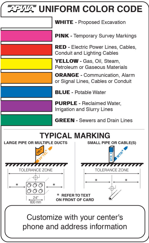
Where regulatory mandates are in place for locating, the American Public Works Association (“APWA”) has established a standard uniform color code for marking different utilities.  It should be noted that dependent upon the country where the work is to be performed, different color codes maybe used.

Example: In Australia, the following is used: Orange = electricity; Yellow = gas; Blue = water; White = communications; Red = fire services; Cream = sewage; Purple = reclaimed water; Silver/gray = steam; Brown = oils, flammable liquids; Light Blue = air; Pink = unidentified services; and, Black = other liquids. 

As with the rod and sonde process, this is designed as a passive system, in that by itself it does not automate the collection of the subsurface infrastructure.  Rather it is a terrestrial identification system that when tied to paint markings, is visible at the site but has no post-processing supported documentation.

To provide the information for either construction prints or for SUE documentation of existing infrastructure, this passive system must be augmented with GPS data collectors and a storage medium.

One other use of this system is to verify the as-built condition of any new infrastructure, if a metallic pathway (i.e. tracer wire) is placed.  In this manner, the “QA Inspector” can verify the probable true running line and depth of the newly placed subsurface infrastructure.  When the receiver element is linked to a GPS Data collector, automation of the as-built records can be achieved when using a GPS oriented GIS as-built system.

Acoustic Pipe Locating

Acoustic locating is designed to allow for locating of subsurface infrastructure without the transmitter element.  The basic principle is to use sound waves from the surface and to have them reflect back up as they hit solid subsurface elements.  While this creates the ability to ‘locate’ all elements of the underground regardless of a metallic element to attach the transmitter element to, it does not allow for recognition of what type of utility it is.

Use of an acoustic pipe locator is an extremely slow process and should only be used in very small areas, as effectively you must ‘measure’ every 15-to-30 centimeters (6-12 inches) along the whole path you are attempting to locate.  Additionally, you will have to do this in a grid pattern to ensure you capture more than the ±7.62-to-15.24 centimeters (3-to-6 inches) that is directly below the acoustic locator.

Acoustic locators do not interface with GPS data collectors.  As such, if mapping of the subsurface infrastructure is desired, additional equipment and steps will have to be taken to document the subsurface infrastructure.  This additional equipment will consist of mapping grade level GPS data collector and an external tablet with stylus capabilities interfaced with the GPS data collector and having land base map of the area documenting.

Ground Penetrating Radar

GPR is an electromagnetic (EM) geophysical method for high-resolution detection, imaging and mapping of subsurface soils and rock conditions.  The idea of using the propagation of high-frequency EM waves for subsurface investigations can be traced back to the beginning of the century, but the earliest references to the possibility of using sharp EM pulses appear in German patents from the 1920’s.

Ground penetrating radar (GPR) performance is primarily governed by the material being surveyed as radio waves decrease exponentially and soon become undetectable in energy absorbing materials such as wet clay.

This is a physical limit and no amount of instrumentation upgrading will overcome it.  However, development efforts aimed at improving the over-all sensitivity of the system may enhance performance in several circumstances and allow even better results.[5]

The choice of using a GPR system should be understood that it will require trained surveyors and a GIS post processing team.  Failure to understand this will result in the system being worthless.  However, the right level of investment and skilled post processing staff, the information will prove to be invaluable in reducing cost.  It should also be understood the use of GPR is truly the only manner, in which, SUE can be truly accomplished, thus the recognized cost savings is dependent upon the use of GPR.

GPR Explained

A typical GPR system has three main components:  Transmitter and receiver that are directly connected to an antenna, and a control unit (timing).  The transmitting antenna radiates a short high-frequency EM pulse into the ground, where it is refracted, diffracted, and reflected primarily as it encounters changes in dielectric permittivity and electric conductivity.

The propagation of a radar signal depends mainly on the electrical properties of the subsurface materials.  Waves that are scattered back toward the earth’s surface induce a signal in the receiving antenna, and are recorded as digitized signals for display and further analysis.
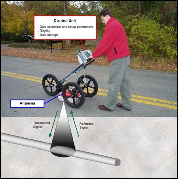
GPR works by sending a tiny pulse of energy into a material and recording the strength and the time required for the return of any reflected signal.  A series of pulses over a single area make up what is called a scan.  Reflections are produced whenever the energy pulse enters into a material with different electrical conduction properties or dielectric permittivity from the material it left.  The strength, or amplitude, of the reflection is determined by the contrast in the dielectric constants and conductivities of the two materials.  This means that a pulse which moves from dry sand (dielectric of 5) to wet sand (dielectric of 30) will produce a very strong reflection, while moving from dry sand (5) to limestone (7) will produce a relatively weak reflection.

While some of the GPR energy pulse is reflected back to the antenna, energy also keeps traveling through the material until it either dissipates (attenuates) or the GPR control unit has closed its time window. The rate of signal attenuation varies widely and is dependent on the properties of the material through which the pulse is passing.

Materials with a high dielectric will slow the radar wave and it will not be able to penetrate as far.  Materials with high conductivity will attenuate the signal rapidly. Water saturation dramatically raises the dielectric of a material, so a survey area should be carefully inspected for signs of water penetration.

Metals are considered to be a complete reflector and do not allow any amount of signal to pass through.  Materials beneath a metal sheet, fine metal mesh, or pan decking will not be visible.

Radar energy is not emitted from the antenna in a straight line.  It is emitted in a cone shape.  The two-way travel time for energy at the leading edge of the cone is longer than for energy directly beneath the antenna.  This is because that leading edge of the cone represents the hypotenuse of a right triangle.
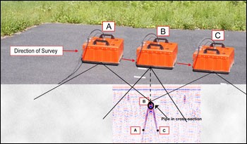
Because it takes longer for that energy to be received, it is recorded farther down in the profile.  As the antenna is moved over a target, the distance between them decreases until the antenna is over the target and increases as the antenna is moved away.  It is for this reason that a single target will appear in a data as a hyperbola, or inverted “U.”  The target is actually at the peak amplitude of the positive wavelet.

Data are collected in parallel transects and then placed together in their appropriate locations for computer processing in a specialized software program such as GSSI’s RADAN.  The computer then produces a horizontal surface at a particular depth in the record.  This is referred to as a depth slice, which allows operators to interpret a plan view of the survey area.

In many situations, a GPR operator will simply note the location of a target so that it can be avoided, effective like a radio detection locator.  In these instances, it is only necessary to use a simple linescan format to mark the approximate area of the target on the survey surface.  When desiring a detailed subsurface maps and depth to features (i.e. SUE) will require the use of GPR post-processing software, which applies mathematical functions to the data to remove background interference, migrate hyperbolas, calculate accurate depth and much more.

Conclusion

From a purely economic point of view, the use of SUE does show a solid ROI, USD3-USD21 savings for every USD1 spent on SUE.  Of course, that is one of the challenges, because that is money saved and the convincing of the companies and communities this is difficult at best.  However, those communities that have adopted SUE as part of their mandatory roads and utilities construction projects are benefiting from these savings.

Of course, the question is what is the best technique to use for Engineering?  After all, this is before construction!  So, the answer is all the above, because each has their strengths and weaknesses.  Use of the GPR shall provide greater level of detail, depth, size, etc. however it cannot penetrate all soils plus depending upon soil types it has a depth issue.  However, GPRs does not depend upon any metallic element thus able to find the clay tile and more recently the HDPE piping commonly being used in telecommunications, water, sewer, and electric utilities.

As reflected in the Milan project, the use of historical records is inaccurate thus the use of SUE is critical.

Of course, the common thought is to use construction locates via radio detecting locators, however, this has proven to be only partially reliable, considering the number of utility strikes that occur.  However, with utility strikes occurring on average every 60-seconds in the US, the current techniques have been proven numerous times to be faulty.  The addition of subsurface utility engineering at the ENGINEERING phase is needed.  The ROI has been shown over a 18 year period, and they only improve not level out, so the time is now for implementation of SUE as part of the design process.  The use of the proper survey tools and post-processing software & analysts is critical to make the SUE process valid.

So, what company is willing to stand up to this ‘Call to Action’ and begin doing the right thing and reducing its costs – both direct and indirect costs?


References

  • Subsurface Utility Engineering in Ontario: Challenges & Opportunities, A report to the Ontario Sewer and Watermain Contractors Association, 2005, Osman H & El-Diraby TE
  • Utilization of Subsurface Engineering to improve the effectiveness of Utility Relocation and Coordination efforts on Highway Projects in Ontario, September 20, 2006, Arcand L & Osman H
  • Right of Way and Utilities Guidelines and Best Practices, AAHSTO, January 6, 2004
  • A guide for Accommodating Utilities within Highway Right-of-Way, AAHSTO, ISBN 1-56051-306-3
  • Standard Guideline for the Collection and Depiction of Existing Subsurface Utility Data, ASCE 2002
  • Integrating Subsurface Utility Engineering into Damage Prevention Programs, 1994, Anaspach JH
  • Developing Best Practices for Avoiding Utility Relocation Delays, ASCE 2005, Ellis JR, RD & Lee S
  • Subsurface Utility Engineering, March 8, 2002, US Federal Highway Administration
  • Cost Savings on Highway Projects utilizing Subsurface Utility Engineering, 2000, US Federal Highway Administration, Lew JJ
  • ROI of up to $21 per dollar invested in improving accuracy of geolocation of underground utilities, June 6, 2003, Zeiss, G
  • Explanation of the use of 3D GPR for SUE: https://www.youtube.com/watch?v=5ZRBU5wsVdc
  • GPR Introduction from GSSI: https://www.youtube.com/watch?v=oQaRfA7yJ0g
  • Economic Development in New Zealand: GPR use in SUE: https://www.youtube.com/watch?v=COVY_2g-0Go
  • Ingegneria Dei Sistemi Opera Duo GPR: https://www.youtube.com/watch?v=-b0Wr5eATDk
  • Soil Mechanics and Foundations, Third Edition, Muni Budhu, ISBN 978-0-470-55684-9, 2011

[1] Https://www.fhwa.dot.gov/programadmin/pus.cfm

[2] This significant higher return on investment when compared to the Purdue and Toronto studies is thought to be a result of maturation of process and possibly a consideration of the qualitative savings.

[3] GPR seems to work better in the EU because the transmitter power is not as restricted as in the US

[4] Unlikely as improperly marked locates is one of the major causes of utility hits, but not the only, as many times due to Contractor negligence utilities are hit.  By the way, these are the same Contractors you are counting on providing quality ‘As Built’ records.

[5] A European funded R&D project is underway called Optimized Radar to Find Every Utility in the Street (ORFEUS), to which PG&E (California gas and electric operator)

Author: admin | Date: April 26, 2017 | No Comments »

Key in the deployment of any fiber-to-the-X (FTTx) passive optical network (PON) infrastructure is to maximize the number of units attached to a single optical distribution network (ODN).  A greater number of units attached to the ODN reduces the overall cost per unit.  But also, key is to create a passive network that is flexible to adjust to the growth and bandwidth demands of the subscriber base. The use of micro-duct introduces flexibility that is not easily achieved with traditional build techniques.  These are inclusive of:

  1. Passive System Attenuation (PSA) losses
  2. Optical-Signal-to-Noise Ratio (OSNR)
  3. Financial cost for and types & quantities of materials
  4. Maintenance costs (Operational Expenditures)
  5. Defer fiber optic cable costs till ‘take-rate’ requires
  6. Allowing for creation of redundancy
  7. Allowing for use of fiber optic cable only upon subscription
  8. Reduces and or eliminates field splices by allowing ‘home runs’ from the fiber distribution hub (FDH)/fiber access terminals (FAT) to the subscriber optical network terminal (ONT)

Of course, there are drawbacks with the use of micro-duct, some of which are:

  1. Lack of wide experience for the installation and maintenance
  2. Specialty equipment and tools needed for installation and maintenance
  3. Different types of fiber optic cabling requiring retraining of technicians on how to work with

It should also be understood that the use of micro-duct is not limited to underground applications.  It can also be used in aerial applications.  Albeit a bit more difficult with transitions and dips due to bend ratio it is still very much viable.   This paper is focused in on underground applications, however the same philosophy can be applied to aerial applications.  The only thing that truly changes is the device placement and, of course, the construction technique.  However, the savings reflected are applicable to either underground or aerial use of micro-ducts.

Fig 1

Figure 1: Typical OLT to FDH Route

A typical FTTx route will:

  1. Start at the optical line terminal[i] (OLT) (C1) – feed to the equipment optical distribution frame (ODF) (C2) normally via fiber optic patch cords.[ii]
    1. Should be noted that the connection at the equipment is also a point of high optical signal-to-noise (OSNR) ratio due to back scattering and reflectance.
    2. When calculating the overall cable length, the length of this cable (or patch cord) must also be taken into consideration.
  2. From the equipment ODF, a fiber optic patch cord is then ‘jumped’ over to the outside plant ODF (C3).[iii]  The outside plant (OSP) ODF normally will have a cable stub out, thus the connectors are factory terminated at the ODF.
  3. The OSP ODF cable stub out will be routed to the zero manhole[iv] where it is fusion spliced (S1) to the outside plant fiber optic cable (OSP-FOC) which is routed to the respective fiber distribution hubs (FDH).
  4. Depending upon length of the route and the fiber optic cable reel length, an intermediate splice (S?) might be required.  The overall outside diameter of the cable will determine the total maximum length that cable reel[v] can hold.  When ordering cable or pulling cable reels from the warehouse, care should be exercised to attempt to get proper lengths to minimize fiber splicing requirements.
  5. The final point is the fiber distribution hub (FDH).[vi]  There are many configurations of the FDH.  Some that are in splice enclosure structures that can be placed below-grade or aerially, some in cabinets, and some in pedestals.  It does not matter what the outer structure looks like, they all perform the same function:
    1. Termination of the Distribution Feeder (DF) into a DF patch panel (normally a stub out is provided so to splice (S2) the DF to the OSP FOC).
    2. The DF patch panel is then ‘jumped’ to the splitter (1:2, 1:4, 1:8, etc.)  (C4).
    3. The splitter then splits the signal and is connected via factory terminated connectors to a coupler on the access fiber patch panel.
    4. The AF patch panel is then ‘jumped’ from the split ratio ports to the access fiber (AF) optic cable (C5), which is normally a cable stub from the access network patch panel which is then spliced to the access network OSP cable (S3).

Fig 2

Figure 2: Typical example of Access Fiber Routes using MSTs

The typical access fiber network consists of:

  1. Starting at the FDH, the access fiber cable is spliced (S3) to the FDH access fiber patch panel stub out and is run to the fiber access terminal (FAT).
    1. The total number of FATs is determined by the number of strands within the access fiber optic cable and the targeted number of units to be served by that access fiber cable.
    2. At the FAT, a splice enclosure is placed and the multi-service terminal (MST) fiber optic tail is spliced to the access fiber cable strand.
      1. Based on the MST split ratio will determine the number of units served by that access fiber strand, which is connected back at the FDH split ratio.
      2. The MST is the final split ratio of the optical distribution network (ODN) and is connected to the served units via drop cables (i.e. DLX).
      3. To ease the distribution of the DLX cables, drop vaults are often placed too allow servicing the respective units, thus decreasing the complexity when connecting subscribers after the build project is completed.

The above reflects the most common typical configuration for FTTX network using traditional HDPE conduit and a high-density multi-strand fiber optic cable, with FDH and MST connecting the subscribers back to the OLT, thus creating the ODN. The use of multi-duct can provide alternatives for each or both configurations, which shall be addressed below.

Fig 3

Figure 3: Typical Distribution Feeder Network to FDHs

Figure 3 (above) shows a typical distribution feeder network that uses a tapering process for the fiber optic cable and SDR11 HDPE inner-duct for placement.[vii]  As shown, without considering any reel-end splice requirements, this requires twenty-seven (27) splice points which results in losses and mid-span cable sheath breaks. Taking into consideration the exact same configuration but replacing the tapering fiber optic cable and SDR11 HDPE inner-duct with a 7-way 14/10mm micro-duct would allow for elimination of some fiber cable splices.  As reflected in Figure 3, a target of 72-fiber strands to be delivered to each FDH with the fiber optic cable being placed in 2-inch SDR11 HDPE inner-ducts.[viii]  Fiber optic micro-cables, with up to 192-fiber strands, are available that can be placed into the 10/14mm micro-duct.  This allows for a ‘home-run’ of the fiber optic cable directly from the Active Shelter to the FDH.  As shown in the below diagram, this would eliminate most of the cable-end splices and all the cable sheath breaks and fiber strand extractions, effectively making only 4 cable-end splices required. When considering cable preparation time and splicing this is a potentially significant cost savings, as well as time savings.  Take this aspect and the materials (splice enclosures, trays, etc.) and the passive system attenuation losses of splices and this reflects a potential technical and commercial savings.

Fig 4

Figure 4:  Micro-duct Distribution Feeder Network to FDHs

Figure 4 (above) reflects the following type of micro-duct and fiber architecture:

  1. From the Active Shelter, placement of a 7-way 14/10mm micro-duct bundle and extracting one (1) micro-duct tube at each FDH.  With this architecture, there are six (6) FDHs along the route, thus there would be one spare micro-duct for future use or specialties along the route.
    1. With the use of the 14/10mm micro-ducts, fiber optic micro-cables can be used.  Micro-cables come with up to 192-fiber strands, as such even should additional fibers be needed at the FDH for specialties, it does not present a limitation on a normal basis.
    2. One 14/10mm micro-duct tube is allocated to one of the FDHs.  If additional capacity is known at the time of design, different sizing of fiber optic cable can be specified thus not even mandating use of the spare micro-duct tube.
    3. Placement within the 14/10mm micro-duct tube of a home-run fiber optic cable allows for reduction of cable sheath breaks, which weakens the integrity of the cable, as well as either eliminating the need to ‘taper’ the cable along the pathway (Figure 3) or non-tapered resulting in excessive ‘abandoned’ fiber strands along the route.
      1. Of course, this does result in a larger amount of fiber cable due to the home run nature from each FDH back to the Active Shelter, as such this could result in a bit higher cost, but this cost must be compared to the commercial savings in labor (splicing) and materials (splice enclosures, trays, etc.).

i.      An alternative is to use a higher fiber strand rate in the micro-ducts and to taper the cable as required thus reducing some of the footage and even potentially the number of micro-ducts required to serve.  There are many options.  You just must think through the objectives and impacts.

  1. With the air-blown solutions, the use of micro-duct and micro-cable, cables can be placed with considerably longer distances without tension relief, thus reducing the number of tension relief vaults required.  Additionally, the duct branch closures can be direct buried, as a properly installed micro-duct joint, should not require any future maintenance or reopening.  This improves the public acceptance of the infrastructure as it does not create consistent aesthetically displeasing vaults.
  2. As this is for FTTx applications, many times the distribution feeder routes shall be run adjacent to the access fiber routes.  As such, due to the nature of normal DF fiber, slack loops are placed in various vaults that it runs through but this requires larger vaults to be put into place, even though the access network does not require it.  The use of micro-duct, even with a duct closure mandate, the typically smaller access vaults are satisfactory, thus not requiring larger aesthetically displeasing vaults to be dominantly placed.
  3. The placement of a ‘spare’ micro-duct tube, along the whole distance, allows for growth should the number of fiber strands originally allocated prove inadequate.  Using the spare tube and blowing in larger fiber cable to the targeted FDH, allows for placement to occur without new civils work, without the potential of damaging the existing cable, reduction of fiber splices, etc.  Then, once the new cable is active and cut-over, the old micro-duct tube can have the fiber cable removed and become the spare micro-duct tube for all the FDHs. And of course, if all the FDHs need upgrading, this process can be repeated for each FDH.

Figure 4 (above) reflects purely replacing the distribution feeder infrastructure but keeping the core FDH architecture in place.  While this does allow for improved performance, it does still introduce the losses at the FDH.  While this is a significant improvement, it is not the final or ultimate solution.[ix] One challenge can be that companies have already made an investment in the distribution feeder environment and placed the traditional distribution feeder architecture (Figure 3) already.  As a result, the above micro-duct solution may not be a potential to be used, thus the only place that might justify visiting a micro-duct solution is in the access network infrastructure.  This is understandable and will be explored below. Figure 5 (below) shows the continuation of the concept of using a high-density FDH terminating the distribution feeder and creating the access network.  In a future article we will explore the concept of elimination of the high-density FDH to an alternative that the use of micro-ducts allows.   This would reduce costs associated with these high density FDHs as well as other materials and labor costs.  One of the key factors that these alternatives provide is addressing the aesthetics within the neighborhood after the build project is completed. In consideration of Figure 3, the target is for each FDH to serve approximately 768 units, with a target of the ODN split ratio to serve at least thirty-two (32) units.  To achieve this, and in consideration of the normal topography of the access network, the following is one of the ways to address a micro-duct solution feeding from a high-density FDH configuration as shown in Figures 3 & 4 above.

Fig 5

Figure 5: Access Network Solutions using Micro-duct

Figure 5 shows three different solutions for serving the respective serving area via micro-ducts.

  1. Leg A utilizes a 4-way micro-duct bundle.  This is a good application when the allowed running line allows for placement of the fiber access terminals (FAT) vaults so that the micro-duct route goes directly through the vaults.
    1. Albeit this does mean a bit more work to perform mid-span breaks in the conduit bundle and using enclosures that increases the cost of the service.
    2. Another reason to use this method is when figuring cost for placement, on a normal basis the charge is for opening the trench/bore + one conduit, any additional conduit there is an ‘Adder’ fee, thus this would prevent the adder fee potential.
    3. Leg B utilizes a 2-way micro-duct bundle, thus providing 100% redundancy to each FAT.
      1. This is a good application for when the FAT vault is not in alignment with the approved running line as this will eliminate any splicing of the conduit that would be required as in Leg A.
      2. This method also provides the greatest ease to add ‘new’ fiber to the FAT should the need arise in the future.
      3. This could increase the cost for placement as unless it is negotiated to have multiple micro-duct bundles placed at the same time with staged interruptions, then ‘Adders’ could apply to this configuration.
      4. Leg C utilizes a 1-way micro-duct bundle to each FAT.  Unlike Leg B, this configuration provides no redundancy or non-disruptive growth potential.
        1. This is a good application for when the FAT vault is not in alignment with the approved running line as this will eliminate any splicing of the conduit that would be required as in Leg A.
        2. This could increase the cost for placement as unless it is negotiated to have multiple micro-duct bundles placed at the same time with staged interruptions, then ‘Adders’ could apply to this configuration.
        3. These solutions use a 7/3.5mm micro-duct.  This will allow a Nano-cable of up to 12-fibers to be placed from the FDH to the FAT.
        4. Within the FAT a small fiber access terminal can be placed that could be the first split ratio, a spliced fiber from the FDH to the MST, or last split ratio with home run drop cables.

Of course, this does not get the fiber optic cable to the subscriber unit.  So, let’s explore the final leg of taking the fiber from the FAT to the subscriber units, following the premise of Figure 3, a centralized high-density FDH.

Fig 6

Figure 6: Access Network using Micro-duct: FAT to MST to ONT

Figure 6 reflects from a single FAT that a total of sixty-four (64) units can be served using the Figure3 centralized FDH to serve 768 units.  Additionally, it continues the trend of using the hardened MST as the last splitter point.

  1. With the FDH using a 1:4 split ratio and having 12f delivered to the FAT, a total of three (3) 1:4 split ratio can be served from the FAT.  However, as a normal rule of thumb, the desire is to always provide spares, so instead of utilizing 100% of the fiber split, 8-fibers will be allocated with the remaining 4-fibers designated as spare or special usage fibers at the FAT.
  2. From the FAT, a 1-way 7/3.5mm micro-duct shall be placed to the MST vaults.  The MST pigtails shall be routed through these micro-ducts to the FAT where they will be spliced to one of the allocated fiber strands.
  3. From the MST vault:
    1. Two (2) 1-way 7/3.5mm micro-duct shall be installed to the nearest units to the MST vault.
    2. One (1) 2-way 7/3.5mm micro-duct shall be installed ‘across the street’ to a drop vault (DV).  (Refer to Figure 6)
    3. From the Drop Vault, two (2) 1-way 7/3.5mm micro-duct shall be installed to the nearest units to the MST vault.
    4. From the MST designated port, each served unit (total of 8) a drop cable shall be installed that on the MST side has a hardened connector and on the units’ optical network terminal (ONT) a terminated ferrule.[x]
      1. The terminated ferrule end shall then have the jacket and boot placed by the installing technician.

As has been reflected above, there are various means to use micro-ducts within the FTTx architecture that if properly planned and installed can result in cost savings and technical improvement.  Future articles shall explore more detailed end-to-end solutions and costing models.  However, it is hoped that this article gave the readers ‘food-for-thought’ on methods that could be used to improve their FTTX architecture.


[i] The OLT is the active equipment that is connected to the optical distribution network (ODN) which allows for the subscribers’ optical network unit (ONU) to be provided with the specified services.
[ii] While this might be the common practice, it is not the proper or best manner, use of factory terminated distribution cable should be the preferred method of installation between the OLT and the equipment side ODF.
[iii] It is possible to eliminate the Equipment side ODF, depending upon the size of the supported network.
[iv] Zero manhole is typical to reduce the congestion within the active shelter as such is normally within the controlled environment that is created within the shelter area.
[v] Cable reels come in different sizes, but the most common reel size is 8-feet (96-inch) flange.
[vi] Whether this is an above ground cabinet, below-grade FDH enclosure, or aerial FDH enclosure, they all represent the point where the distribution feeder ends and the access fiber begins.
[vii] Tension vaults and mid-span splices & splice vaults are not shown.
[viii] One inner-duct for the fiber cable and one as spare.  The spare is a normal rule of thumb for placing a spare along any main route for future growth requirements.
[ix] A follow-on article will be forthcoming, reflecting what could be the ultimate solution for using micro-ducts within the whole solution.
[x] If attempting to have hardened connectors on both ends, a minimum conduit of 1.25-inches is required per manufacturers recommendation.
Author: admin | Date: April 12, 2017 | No Comments »

nevada_rural

Federal government broadband initiatives of loans, grants, stimulus funds – all a horrendous failure.

Major carriers and MSO’s – not interested – however will do everything they can to impede alternatives.

Google Fiber – Tier 4 cities and up target – failed and not interested.

With these considerable failures or lack of true interest, then how do we get high-speed broadband service to the rural market where it is seriously needed?  Simple.  We must be self-reliant and not depending upon external entities to make this a reality.  No matter how much they talk about doing it, it is always talk and half measures.

So, that leaves it up to the rural LEC, communities, and cooperatives.   Now then the question is, which of these is most likely to be successful and accomplish this in a timely manner?

To date approximately 150 communities have built out municipality owned and operated broadband networks.  And it should be noted that of these some have been highly successful.  However many have been abysmal failures, resulting in a high cost to the local taxpayers.  Additionally, communities are not truly successful with telecommunications services, with the possible exception of those that are already providing electrical service.  It is these communities that have had the best success, but even then, failures are occurring.

Many Rural LECs are attempting to provide service through their regions and then opening CLEC service outside of their incumbent areas.  While this has proven to be beneficial, even they are ignoring the truly rural market, and predominantly only providing service within city/village limits.   As such, they are not attempting to provide the service to the true rural market.

So, what is the solution?  A new type of cooperative that is focused on creating a broadband network that addresses the rural market.  Creation of a broadband cooperative that designs, builds, and operates a fiber optic network infrastructure that provides:

  1. FTTx connectivity within the cities/village city limits and rural homes along designated routes
  2. Provides a fiber optic backbone interconnecting these cities/villages
    1. Using this interconnecting backbone to allow for connecting rural homes along the backbone route
    2. Fronthaul/backhaul for mobile towers
  3. Fronthaul/backhaul for wireless services for rural homes not along the fiber route
  4. Within city/villages, provide WiFi level services within the main business district

The establishment of these type of rural broadband cooperatives is key to providing high-speed broadband services to rural America.  So, the question is how to enable the establishment of these rural broadband cooperatives, as funding sources are unlikely to be easily raised.

The following financing model would allow for all parties to have ‘skin in the game’ while also allowing for establishment of the cooperative needed seed funding.

  1. Each community that is in the proposed serving area, provides a subordinate loan based on ‘general obligation bond’ that is valued at approximately $500/$750 per person within the city/village limits (i.e. city population of 1,000 people the city/village shall commit $5-$7.5Million as seed fund loan to the cooperative)
  2. Based on the communities’ seed funding, the Cooperative will work with local banks to receive capital loans for the total cost of the build program, broken down into multiple phases
  3. Use of revenue generated from predecessor phases, deferring repayment of communities subordinate loans until the build program is completed in all of the start up communities, and the company has become cash flow positive able to pay its operation and capital loans
  4. Growth of the network into additional communities will occur only after 100% coverage of the startup communities and service is available to these communities and rural marketplace, albeit payback period might not have been achieved but operational cash flow should be achieved
  5. Once established and revenue forthcoming, then organizations like the CFC and RTB could become sources of expansion funds

Key to these models is that maximization of subscriber counts to reduce cost for video content while raising the Internet usage levels but increase of caching and other means will ultimately allow for cost savings as well.

One of the other key aspects that communities would need to provide is right-of-way usage rights.  While the aerial plant in most rural markets are not overly congested, in many circumstances the pole loading would become problematic due to the age of the poles.

Each community would need to be evaluated to see if aerial placement would be the most cost efficient and timely solution.  In many cases while cost might be a savings, time, maintenance, and annual operational costs negates the savings.  In cases like this, and in reality the first thought process, should be the placement of the new fiber optic infrastructure underground.

However, the continued traditional manner should not be adopted.  The use of micro-trenching and use of micro-ducts is a more logical and cost efficient manner for placement.   Communities need to adopt these construction techniques as they represent a significant time improvement and, when accomplished properly, a cost savings.  Of course the key is the means and techniques used for utility locates and reinstatement after the fact.

The key factor this article is pointing out is that high-speed broadband infrastructure is possible for the rural marketplace.  However, out-of-the-box thinking and approaches must be accomplished.  Failure to expand the approach we undertake will keep the rural marketplace without high-speed broadband service.  So the question is, who is willing to undertake the process and make high speed broadband in the rural marketplace a reality?

Author: admin | Date: April 8, 2017 | No Comments »

Everyone loves the idea of a gigabit networks.  Google Fiber started the hype and then all the carriers followed suit creating gigabit networks.  But what exactly does that mean to customers?  Do they know what it will allow them?  And, more importantly, how do telephone companies productize this network investment if all that is being sold is bandwidth?  Very soon it shall become a commodity and then just like voice and short message service (SMS) average revenue per user (ARPU) will begin to degrade thus the ability to obtain a high return on investment (ROI) will be lost.  Hopefully the payback period will have been achieved prior to this commodity view, otherwise the network may never pay for itself.

When the mobile industry started, the focus was on the mobility aspect for voice; the untethered handset that allowed customers to make and receive phone calls from anywhere with their own phone number.   This was then broken down into different offerings – by minutes, local coverage, long distance, roaming, etc.  Thus, emulating the original voice service and then adding the new feature sets that this technology provided.

In 1993, with the advent of SMS, while this was tied specifically to the mobile handset, it was not just assumed to be part of the offering rather we productized it and turned SMS into a revenue generating product.  With the enhancement of multimedia messaging service (MMS), we then starting looking at bandwidth capabilities but also made it into an enhancement of the SMS service offering.

In the mid-late 1990’s smart phones did not really exist instead we used PDAs (personal digital assistants), such as Palm, Blackberry, etc.  Because these PDAs were separate from the voice handset, different product offerings were created for the ‘data’ usage, which was usage driven, just like voice minutes.

In 2003, Blackberry had become the widest accepted ‘smartphone’ and even had its own colloquialism assigned to it like ‘CrackBerry’.  Telephone companies sold this service and it was predominantly focused on voice and email services.  Again, everything was usage based.   From 2003 – 2007, a variety of ‘smartphones’ were developed by various companies but the Blackberry was the dominate handset of choice.

In early 2007, Apple introduced the first iPhone, which started the smartphone revolution.  Now the smartphone could handle voice, SMS/MMS, email, but also web browsing, and the key was that it mandated a standard voice plan plus a data plan.  Now the data plan was based on usage while the voice service had become commoditized thus was not minutes or usage based as previously.

So, from 1987 to 2007, voice and SMS/MMS has become a commodity product that will not allow for new ‘productization’ of, but rather is now viewed as a means to an end to obtain smartphone data usage.   Now, in less than 5 years, there are data-only product offerings for ‘smartphone’ users, eliminating the voice and SMS/MMS revenue stream.

What does this tell us?  If we approach the gigabit networks, and yes 5G, as we have we will be seriously limited in how to achieve our payback periods and to have a solid ROI.  The sooner a technology becomes a commodity, the less likely the targeted ROI and future greater revenues can be achieved.  Because just as with the advent of the xDSL, 3G, and LTE networks, the customers expected greater service capabilities but at a lower price.  As such, to achieve these demands, we the telephone companies must significantly increase our fronthaul/backhaul networks.  However, instead of being able to increase our revenue when doing this expensive network upgrade, we instead must offer greater service capabilities but at a lower cost.

As such, with the new growth factor that we are experiencing with the gigabit networks, we need to head off the current trend of selling ‘bandwidth’ and refocus it on selling enhanced product offerings.

What do I mean by this?  Glad you asked.  So, if we look at the eventual adoption of 5G and the IoT (internet of Things), as well as the continued growth of LTE, as well as gigabit fixed line networks, we need to look at the usage patterns of our customers, not just bulk bandwidth.

Once we understand how our customers are using the network, then we can create products focused in on offering this in an enhanced mode.  Examples of packages could be:

  1. Optimized for YouTube, Social Media (Facebook, Twitter, LinkedIn, SnapChat), and OTT (over the top television)
  2. Optimized for Email, standard web browsing, Facebook, and HDTV viewing

These are just examples of productization that can be achieved.  Once we decide to accomplish this type of productization, then we depart from selling ‘bandwidth’ and instead offer enhanced services at varying price points.  Yes, this will require that we think about how we design and build our back office and network capabilities, maybe have more video caching, use of IP Sockets, etc. to allow the network to offer these enhanced services, but it would allow us to productize rather than commoditize our network offerings.

With the continuation of the bandwidth model that we are trending toward, the ability to recover cost and be profitable is seriously in jeopardy.

Author: admin | Date: April 7, 2017 | No Comments »

“He who fails to plan is planning to fail!” Winston Churchill

One of the greatest faults that exist in any project is the failure to plan!  Studies (and real-life) show consistently if a project is not well planned, it will result in unexpected events, that normally cost money and time.  In my past 38 years in the industry, I have taken over numerous projects that had the original philosophy:

1)      Management identified the need (budget, schedule, product)

2)      Project Manager begins executing

3)      Management expectation is not being achieved

4)      Project either fails or comes in over budget and behind schedule thus fails

Or in other words: Shoot – Aim – Wonder why you didn’t hit the target

However, nowhere in this mix was the process of PLANNING the project.  Of course, there are the other type of projects where the Project Manager uses a series of ‘templates’ to plan out the project based on personal experience or what was estimated at time of project conception.  What this activity accomplishes is a Gantt chart with a series of major milestones with a duration and sometimes a budget or resources, linked to that milestone.  Sounds good, right?

Wrong!  This is even worse than executing without a plan.  Why?  Because your measurement metric is at such a high level you will never know when and why a problem affected your project cost or timeline.

One of the flaws with most project management training and books is the view that plans at a macro level not a micro level.  While this might be valid in major building or highway programs, this is seriously flawed for telecommunications projects!

Why do I say this?  Activities that constitute a telecommunications project that have a roll-down affect to the project are normally of very short duration; sometimes less than a day.  As such, if you are not tracking and monitoring these tasks and sub-task; then when one of these items is not accomplished properly (on-time and on-budget) the overall impact to the project is not able to be measured.

What does not being able to measure the impact mean?  Let’s take an example:

The project is an FTTH outside plant underground placement of conduit and fiber optic.  In a standard milestone project schedule, you would plan to have a 3.75-mile segment accomplished within 42 calendar days.  Sounds reasonable, right?  However, what happens if the contractor only places 500-feet per day of conduit? 

Can you tell me the impact to the project? When will the fiber optic cable be placed?  When can you test the fiber segment(s)?  When can it be Inspected?  When is the sub-segment ready for service?  When can Sales & Marketing, commit for connectivity?  When can you start having drop cables installed to the homes?  When can Operations accept the sub-segment/segment?

A 500-foot per day conduit production rate would require 40 work days not calendar days. However, 40 work days would require working 7 days a week for 6 weeks.  This is unlikely to be approved by the community (assuming working in town) as well as the construction crews’ willingness to work, possibly at a fee.  Does your budget allow for this?  The reality is that you have 30-working days in a 42-calendar window thus the production rate would need to be 660-feet per day.  Again, does not seem unreasonable, right?

Unfortunately, a lot of dependencies exist to achieve this type of production rate – construction techniques, soil conditions, make ready requirements, traffic management, locates, work hours, materials, inspections, etc.  As these are items that have a serious effect on the production rate, they need to be identified and tracked!  As such this single milestone line item in the Gantt chart is now needs to be broken down into at least five contributing tasks to achieve this daily production rate.  However, if you still do not break the production rate down to the lowest level (i.e. daily), you will just be placing a duration against these contributing task elements and should you tie dependencies to these then you will see that 42-calendar day window be blown out considerably. 

Note: Of course, more crews could achieve this, but then what are the restrictions for the number of crews working imposed by the community?  Could this cost more and could your budget support additional crews?  Do you have adequate materials to support multiple crews?  Can locates be accomplished to address more crews; etc.  There are lots of different additional aspects when throwing resources to ‘solve’ a problem.  So no, the old AT&T adage of:  If you have a thousand man-hour job, put 1,000 people on it and it will be accomplished in one-hour; cannot and does not apply to any project!

As such, planning is not just creating a milestone chart of quantified product, rather it is the developing of a detailed series of daily task/sub-task[1] that has time (duration), cost, resources (materials, manpower, equipment, tools), and dependencies linked to them.  Without a daily view of activities then no measurement will be accurate, thus result in a FAILED project due to over-budget, behind-schedule, and quality compromised.

As a Project Manager, whether you are working for a telephone company, construction contractor, or supplier, you are always behind the eight-ball.  You are assigned to a project and the budget and schedule is already set, as well, a set of expectations.

However, these budgets and schedules are normally established at a gross order of magnitude by people who do not always have the full picture of what it will take to work in the build environment.  As such, the quandary of a Project Manager is to validate the assumptions to properly deliver the project.  However, if the Project Manager does not PLAN then they have no way of validation of the assumptions.  And if the Project Manager does not plan to a granular level, they will never know what the true budget, schedule, and resources are to achieve the targeted product and associated quality.

The challenge is that when the Project Manager assumes the project, the ‘clock’ normally has started.  As such, the time schedule for planning is not present.  With this situation, most Project Managers feel that they must: EXECUTE – PLAN ON THE FLY – DELIVER which ultimately means FAILURE rather than success.

And unfortunately, this is the manner most telecom projects are handled!  Just so that everyone is on the same page, this approach is NOT Project Management, this is execution failure.

When I say ‘failure’ it does not mean that the project is not delivered.   What it does mean though is that the original business plan costing model cannot be achieved, either due to delay in revenue generation, cost overruns, or quality does not meet customer expectations.  But also, one other aspect of project failure is the impact to potential customer/community perception of the project.  As an example:

Google Fiber was highly expected and desired by the communities.  However during construction in Austin, San Antonio, etc., due to the construction process, the customer/community perception of the value that Google was bringing was seriously degraded, to the point where the potential customers were no longer interested in having them around!

What needs to be fully understood is that the “failure to plan is planning to fail!”  And with telecommunications projects the failure has a wide variety of impacts, from cost all the way to being able to sell the service the infrastructure was designed to offer!  Unlike the more commonly known wireless projects where the work is isolated to just the tower locations, a FTTx project shall effectively touch every street in the targeted community.

Project Planning cannot be excluded from the process rather it must be the process.  The ‘devil is in the details’ approach must be undertaken when developing the project plan for a FTTX network, otherwise the project will fail and that failure will result is seriously detrimental consequences to the company.


[1] Some may view these as daily checklist, thus not something that should be tracked in a project plan, however, using ‘Excel tracker’ or even a non-linked checklist form will result in loss of insight of the true impact these items have to the project timetable and cost.

Author: admin | Date: April 3, 2017 | No Comments »

On May 20, 1936, the US Federal Government passed a major piece of legislation, the Rural Electrification Act (REA), that instituted a low-cost loan and grant program to bring electricity to Rural America.  This legislation was a major game changer for Rural America.  Since then, nearly 100% of Rural America has electricity.

A key factor in the success of this legislation is the focus of providing funds to the cooperatives, not the larger electrical providers located in the Tier 1, 2, and 3 cities.   In 1936, it was recognized that the cooperative model was geared to support the true rural marketplace, which was later reinforced in 1949 when the REA was authorized to provide low-cost loans to rural telephone cooperatives.

Now in the year 2017, the Federal Government has become bloated and so full of red tape that the ability of rural entities to use the federal grants and loans to bring a highly-needed broadband service to Rural America is extinct.  The Federal Government stimulus and broadband loans/grants have proven to be worthless to the true Rural Market.  As such, the US Citizen’s federal tax dollars are spent without a true return to America – shame on our government!

Due to the red tape and cronyism within these federal departments, the funds never make it to the marketplace that it was supposed to be targeted for, Rural America!  To believe that the major carriers and MSOs will take these funds and build into the low-density markets, Rural America, shows a major failure of the Federal Government to understand capitalism.  Unlike the 1936/1949 model of recognizing that rural cooperatives will provide this needed service to Rural America, the Federal Government focused the loans and grants to the larger carriers!

These carriers are using the funds to expand their networks in the “NFL” and Tier 1 & 2 cities, and then providing pseudo services to the Tier 3 cities, but to Rural America – goose eggs!  Yes, good for the carriers as it improves profits and services to the city dwelling people, however, the whole concept was to ‘emulate’ the REA thus getting broadband services to nearly 100% of Rural America.

Per the FCC Jan 2016 report, 39% of Rural Americans (over 23 million people) lack access to 25Mbps/3Mbps service, which is the new metric for broadband service.[1]  If you look at this statistic it does not seem so bad, right?  However, what it does not show is the number of Americans that, due to poor infrastructure, have left Rural America to go to the ‘cities’ which may not seem like a bad thing.  But as Americans leave Rural America, so does the ability for America to grow its own food, vegetables, fruit, and meat!  Additionally, this creates a job market demand in the cities that might not be able to meet that demand, thus increasing the growth of unemployment or under-employment.  Once the dominoes begin to fall, it is very difficult to predict the total impact to the US Economy.  Besides the economic impact to America, this mobility also degrades the family unit, which can be seen as no longer is the family a key focal point within the USA.  Why is the breaking up the family relevant?  It is normally the younger generation that demands the broadband service to participate in the ‘Information Age.’  As such, the more they depart Rural America due to substandard infrastructure, the quicker the ability of the US to provide for its own food requirements is seriously degraded.

Additionally, the failure to have the broadband services in the true Rural America, education is degraded.  In the ‘cities’ broadband services are available thus improving the knowledge and information access for educating America’s future.  However, due to the substandard infrastructure in Rural America, ‘rural’ children are not getting all the benefits in education that the ‘city’ children are.  This causes parents to move into the cities to provide for their children.  While items such as the federal government’s ‘E-Rate’ structure have been established to attempt to bring broadband services to schools, truly rural schools are not able to benefit from this offering.  Even if the school has broadband offering that does not mean it is in the rural household, thus still limiting the children.

The Federal Government has spent billions of US taxpayers’ dollars under the premise of providing broadband to Rural America.  However, this has proven to be a complete fallacy, because the funds have been misappropriated, used to pay off debt, or to build out networks in higher density cities, with limited to no funds spent in the true Rural America.  Unlike the 1936 and 1949 acts to address Rural America, the Federal Government focused not on the cooperatives that are serving Rural America, but rather made the rules to receive the funds so onerous that only the larger carriers and MSOs could be eligible for those funds.  And then making the accountability for proof of usage of those funds so limited that these carriers and MSOs have been able to spend it however they felt with limited proof of serving the true rural market.

As such, Rural America cannot and should not count on the Federal Government to bring Broadband communications to them.  It is now time to realize that the government is not and should not be the solution, instead it is the residents of Rural America.  We can be and ultimately will be our own solution.

This paper reflects a ‘Call to Action’ because if Rural America is going to get Broadband, then waiting, or depending upon the government to ‘make it possible’ will only result in the continued degradation of the rural lifestyle.  With the number of rural utility cooperatives, electric and telephone, the ability to band together makes Rural Broadband not only viable but desirable.

We have seen companies, like Google, thinking they could enter the high-speed broadband marketplace but even they failed to view the Rural marketplace as desirable.  They wanted the larger cities and have now failed even in that marketplace due to the lack of comprehension of what it takes to deliver services.

Rural cooperatives do understand how and what it takes to deliver service in these rural markets, and with combining forces the build out of the hybrid fiber/wireless infrastructure to meet the high-speed broadband market can be achieved.

We have seen this model growing with the Indiana Fiber Network (IFN), Iowa Communications Network (ICN), South Dakota Network (SDN, etc. where rural cooperatives and companies have banded together to create a state-wide fiber network.  This model then allows for cooperatives to provide fiber-to-the-X and backhaul for remote wireless hubs in a more cost-efficient manner.

It is these models of out-of-the-box thinking that will bring broadband service to Rural America, not the Federal Government.  Keeping government out of the model is better as it keeps our taxes down, and allows the focus of our neighbors helping one-another model to thrive as it did in the late ‘30’s.

The Rural Utilities Cooperative models use of federal government loans to meet the members needs has proven reliable and a larger percentage of loan debt retirements occurs from the cooperative model then these prior broadband loans and grants, as such the recovery model is also better for the US Taxpayer!

As such, my call to action, is for the US Federal Government to stop giving funds to the larger carriers and MSOs for rural broadband and to make these funds available through a loan program to the rural cooperatives that have proven track record of truly provide service to the rural marketplace!

Author: admin | Date: February 5, 2014 | No Comments »

I had the distinct pleasure of being one of the invited speakers to the BICSI 2014 Winter Conference.  I was allocated 3 hours in the pre-conference period to present to Attendees “Quality in FTTX Deployments.”  They advised me that normally there are 30-40 Attendees in these sessions, but when I got there I was told that 60 had signed up.  When the session began there were at least 50 Attendees present, so I was feeling quite happy with the turn-out, especially as this was Superbowl Sunday!

Now then,  even though this was BICSI which is more focused on inside plant, my course was focusing in on the aspects of outside plant that has a significant effect on the quality of the FTTX network.  However, the session had several Attendees who actively participated and asked a lot of good questions and I believe the other Attendees mostly also benefitted from the session.   I guess the final telling if the Attendees got something out of the course will be the Attendees survey forms which will decide if BICSI invites me back to speak at another conference.

As part of being a Speaker I was allowed to attend other sessions and walk the Exhibition floor.  I must say I was surprised by just how much focus the conference exhibition was on inside plant, but I shouldn’t have been as that is the strength of BICSI but there were minor exceptions that had some interesting OSP products which I did stop and look at.

One of the first items that caught my eye was a company called Nojitech Corporation which is a Japanese company with offices in Canton OH.  They had a product which is a galvanized steel square with built in HDPE ducts for placement of various types of cables.  It is a very interesting concept but there are a lot of questions I have before I would start considering it for any of my projects.  But again interesting concept and worth following to see if they are going to publish any white papers or technical specifications about how it stands up in different soil types, how the gaskets function and lifecycle expectancy (thus how would they be replaced), and of course the most important aspect is in case of damage how can this system be repaired.  Like I say, interesting but lot of questions.

The next item that caught my eye was from a company called McGard out of Orchard Park, NY.    They had a manhole cover system that was made of HDPE and a locking system that required a special bolt and wrench to open.  Now then we are all use to the specialty keyed bolts that eventually due to transition in technicians becomes globally available, but I liked this cover because it is a lightweight manhole cover that still meets the H20 and EN124 specifications and has a unique bolt locking system.  This is a product that in future projects that have manhole cover replacement needs I might very well consider.

Of course any good OSP person will always stop and see what Duraline is now offering, so I stopped.  They were displaying their eABF micro-duct system.  Micro-duct – as an OSP Design/Build company – I have found to be highly flexible and beneficial to my clients and projects.  With the advent of FTTX the flexibility in designing and deploying OSP systems without stranding a lot of fiber without take rate while still preparing for 100% take rate, micro-duct is proving to be a valuable solution.

I was happy to see that K-Net was present as well.  This is a company that I have used previously overseas for micro-duct FTTH (SFR and MDU) solution.  If you are looking for a flexible micro-duct system at a good price point I have found this company to be a good option.  Of course, Emtelle and Duraline are also good offerings, thus allowing us to get the products we want and get at least three quotes to obtain the best pricing for comparable products.  I will state I was surprised that Emtelle was not present at this BICSI Exhibition.

I want to also re-emphasis a statement I made in my session, the use of micro-duct is not limited to OSP, it is also a product for use in FTTD (fiber to the desktop) as well as in MDU for FTTH applications in the riser or riser applications for multi-story office buildings.  This allows us to place the micro-duct conduits in place without stranding fiber assets.

Again any good OSP Engineer will always stop and see what CONDUX International is displaying.  They of course had their standards stuff out but they were also displaying small air blown fiber units designed mainly for inside application for micro-duct .  Interesting products albeit a bit heavy and still needing a smaller air compressor, I think I will stay with the inside plant friction based systems that I can attach a hand drill to.

Like I stated at the beginning the Exhibition was predominantly for Inside Plant so there were a lot of suppliers of cabling, trays, faceplates, etc. but one did catch my eye and that was Vertical Cable out of CA, NY and FL.  What intrigued me was that Rebecca said their cabling was of the same standard as all of the other players (i.e. Graybar, Anixter, etc.) but that on norm they were $30 cheaper per 1000ft box!  If this is true it is definitely worth looking at our supply contracts and see if they can help us and our clients save money!

Overall I was happy that I was able to attend the BICSI 2014 Winter Conference and Exhibition and look forward to the opportunity to possibly present additional sessions on outside plant, optical fiber, and FTTX to future Conferences Attendees.

Author: admin | Date: January 14, 2014 | No Comments »

I remember in the 80s and 90s, when we Service Providers fought against the use of Packet Switched networks and IP.  To overcome the mandates of the data communications networks of our clients we created ATM (Asynchronous Transfer Mode) and said we now have a technology that meets the needs of data communications but also our need for control!  But we were wrong, ATM was just a costly (both in price and overhead) technology that came too late and was too restrictive.

With the advent of the Telecommunications Service Providers adoption of packet switched networks the mandate of using the Internet Protocol (IP) has become a necessary evil.  The driving factors for this has been the continued demand by our customers for higher bandwidth at a lesser cost as well as our (Service Providers) network usage demands with the advent of the mobile and broadband services.  Of course, prior to deregulation of the industry globally, we could charge a higher price and customers would either pay it or do without, which was the mind-set we Service Providers had!  But the market place has changed, deregulation has occurred, and customers are more demanding and we are now in a commodity industry!  Bandwidth is a commodity that can be shopped for!

With this revelation and the increase in broadband services, not only by our clients but also within our own internal networks, we had to adopt technologies and methods that allow us to reduce the cost per bit to obtain the greatest return on our bandwidth investment.

The continued use of circuit switching technologies, like ATM. PDH, SDH/SONet, has become a serious burden on Service Providers when considering the cost per bit aspect.  However, we (Service Providers) have come up with methods to allow Packet Switching over our circuit switched technologies through the use of VCAT, EoSDH, CENoSDH, etc.  However, this is only a band-aid, as we are not overcoming the technology constraints and overheads of circuit switched technologies, thus not achieving the goal of maximizing a reduced cost per bit.

But as in all things telecom – we are taking baby-steps to achieve the goal of a true packet switched network to address the predominant packet based traffic of today.  Numerous studies have shown that the traffic presented to us (Service Providers) by our clients and yes even our own network traffic, is packet-oriented, so the adoption of packet based networking technologies is obvious. But as previously stated, we, Service Providers, have always wanted to have a degree of control, not so much as to what is presented for transmission, but of the predictability of the transmission link.  The best way to achieve that is by having a fixed traffic path through our network regardless of traffic type or even traffic presentation.  It is easier to troubleshoot a predictable event then a sporadic even like packet based traffic.

With the adoption of packet based technologies into our network and recognition of Internet Protocol (IP) as the dominant traffic types, we (Service Providers) have had to accept the bursty (sporadic) nature of the traffic and the transmission link.  While accepting the bursty nature we still have this inherent need for the creation of ‘virtual’ circuits (paths) for traffic allowing us to maintain a degree of quality of service (QoS) that can be achieved easily with our circuit switched world.

Security has been a major concern of our clients for their networks and the associated traffic, thus they two preferred the lack of intelligence of the telecommunications networks previously provided based on ‘circuits.’   But with the increase is traffic volume and distribution of content, our clients need to have more bandwidth, more sites interconnected, but at a price point that is affordable for them.  Point to point circuits no longer adequately address our clients traffic needs.  The advent of packet based networks that provide multipoint level services with dynamic bandwidth is key but also still keeping it at a level that our (Service Providers) clients prefer to maintain traffic and content security.

The creation of Multi-Protocol Label Switching (MPLS) was a step toward the creation of a network that could provide the level of service to the clients while still allowing Service Providers with an ability to ensure traffic path predictability along with improvements on QoS features that previously packet switched networks with IP could not provide.  However, while MPLS supports layer 2 VPN (Psuedowire) it was designed to be optimal at layer 3.  But layer 3 provides a higher level of intelligence of traffic content to Service Providers that many clients do not desire.  Additionally, it potentially creates an environment where greater coordination of QoS features and addressing has to be coordinated between client and Service Provider.  As a result, Service Providers implemented MPLS however the dominant amount of the traffic being presented from clients and our (Service Provider) internal mobile networks is layer 2 traffic.  So in our core network we are able to process traffic more efficiently with the use of label switching we still have limitations on QoS and even a true multipoint structure as our label switched paths (LSPs) are unidirectional and did not support true muti-segment Pseudowire.

We recognized this limitation and the activities of creating GMPLS, T-MPLS, and/or MPLS-TP were started by various entities.  Ultimately MLS-TP, became the accepted standard of the three, thus the other two became somewhat incorporated into the final MPLS-TP standards.

MPLS-TP is a layer 2 standard that addresses the needs of security, switching, QoS, and multi-segment needs of our (Service Provider) clients while still providing us (Service Providers) with a predictable pathway while reducing processing time through our core network.  Additionally MPLS-TP allows for bidirectional Psuedowire within MPLS LSPs overcoming many of the traffic problems occurring with the IP/MPLS unidirectional LSP limitations.

The implementation of IP/MPLS within our (Service Provider) core network and MPLS-TP on the Access Edge network provides us with the greatest capability to properly support the packet based traffic that is being presented to us from our clients and our own internal network traffic (mobile & broadband) thus creating the proper platform for a packet based network.

Once we have implemented IP/MPLS and MPLS-TP structure the next big step will be the true obsolesce of our circuit switched transmission network (SDH/SONet/PDH) and implement a true packet switched network, like a native Carrier Ethernet Network (CEN) operating over Dense Wavelength Division Multiplexing (DWDM) optical network, a true packet based microwave network, a hybrid of DWDM/PON/Packet Based Microwave, and Passive Optical Network (PON) access network.

The time is now –  the technology is proven and stable.  Implementation of IP/MPLS, MPLS-TP, Carrier Ethernet over DWDM, PON, and or Packet Based Microwave is how we – Service Providers will be able to achieve the greatest cost per bit savings while still meeting the our clients and internal network demands.

Author: admin | Date: September 6, 2010 | No Comments »

‎”The mediocre teacher tells.

The good teacher explains.

The superior teacher demonstrates.

The great teacher inspires.”

— William A. Ward